These step numbers follow along with the illustrated installation manual I received from ESS. Red steps indicate what I consider to be difficult procedures. '99-current model 540i's have a fairly different vacuum and breather tubing setup, so many of these steps will not apply.
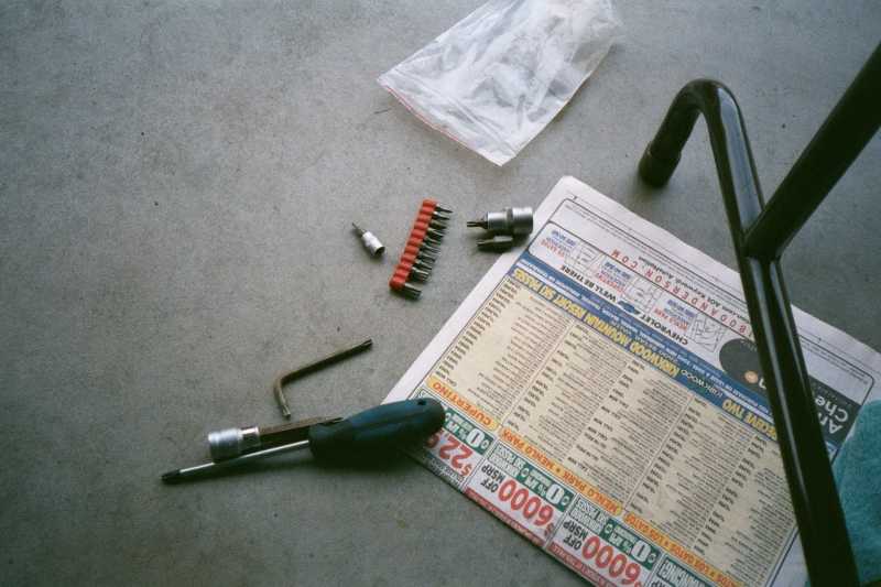
Required Tools (not a complete list):
- 2 floor jacks (small floor jack, as well as stock jack is fine)
- 32mm open-ended wrench and some type of spanner or similar tools (channel-lock pliers) to remove the fan. BMW has their own specialty fan tools that they don't sell to customers.
- A quality set of metric hex wrenches, including 6mm & 10mm hex-head 3/8" sockets.
- A quality set of torx tools, with the front bumper using a T50 and the rear intake manifold cover using a T30.
- A good variable-speed drill.
- An impact wrench might be useful for some of the A/C bolts, but I got by without one.
- A complete set of normal and deep metric sockets in different ratchet sizes.
- Ratchet extensions.
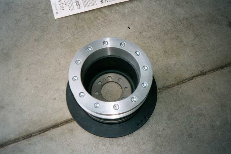
- A complete set of metric open-ended wrenches.
- Loctite.
- Standard garage tools: a variety of screwdrivers, hammer, pliers, wire cutter/stripper, hacksaw, file, etc.
- Work light
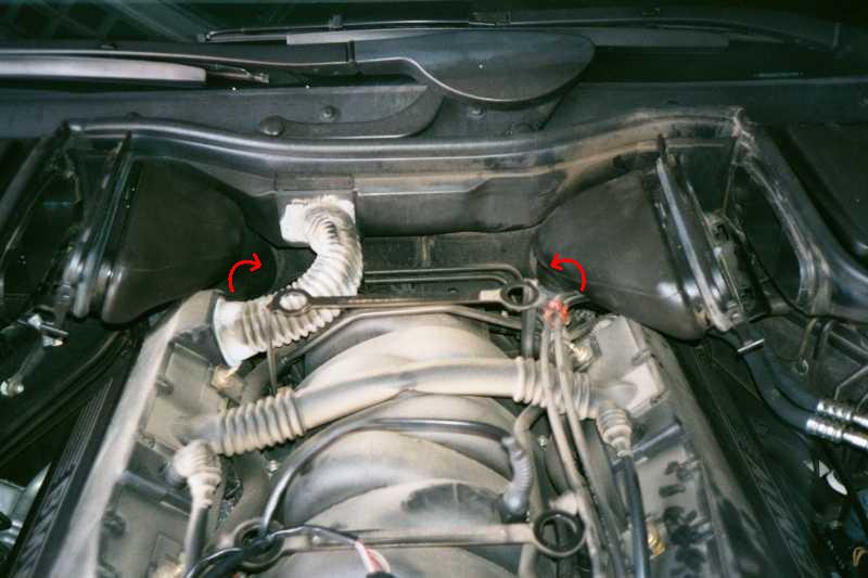
2. Rotate the air ducts towards the center of the car. The fan assembly removal requires a 32mm open-ended wrench or channel locks for the reverse-threaded bolt. I had no luck with removing the bolt, but the ESS tech did it with a pair of channel-locks andhis hands.
3. Front bumper removal requires a T50 Torx bit.
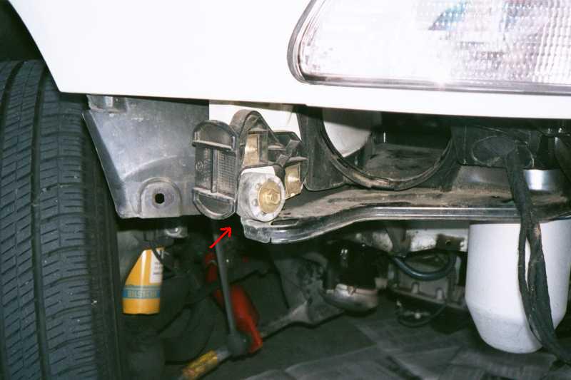
4. Based on the installs I've seen, there is no "exhaust air fan" on '96-'98 US-spec cars. I reused the rubber mount point and bolt from the air intake scoop (under turn signal) to reconnect the metal pieces.
6. A serpentine belt tool might be useful for this step.
8. Based on the installs I've seen, there are no "exhaust air supply tubes" on 1996-1998 US-spec cars.
9. Remove the oil dipstick to allow for removal of the engine mount. Replacing the mount isn't difficult, assuming the mechanic has experience pulling out an M62 engine.
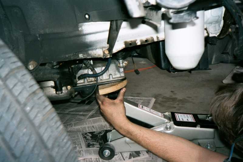
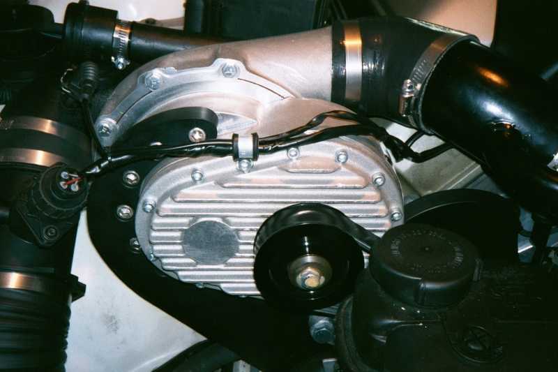
10. Place the new supplied pulley on top of the original pulley assembly and use a rubber hammer to ensure proper seating. Carefully and accurately drill at least 2 pulley attaching bolts. Remove the new pulley and carefully tap the holes. Use both included taps, as they are intended to tap threads at different depths. Once the 2 pilot holes are created, place and seat the new pulley back onto the pulley assembly and use the hex bolts to secure the pulleys together. We used standard (blue?) Loctite on all the hex bolts. If the initial pilot holes don't line-up, rotate the pulley a few degrees and drill new pilot holes. Carefully drill and tap the remaining mounting holes as previously described. NOTE: I'm not really a "machine shop" person, so further questions on this step should be directed to ESS. I do think a drill press would be very helpful for this step. This procedure tends to be fairly time consuming and accuracy is a must.
11. Crank pulley bolt needs to be torqued to 100Nm.
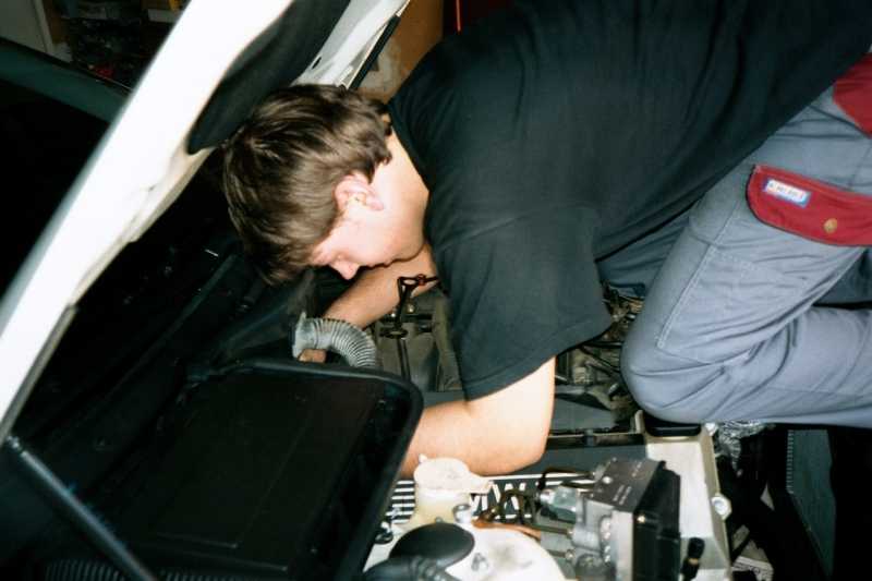
12. The rear intake manifold cover uses (7) T30 bolts. This can be the hardest part of the install because the bolts are very difficult to access when the engine is in the car. They also seemed to be torqued down fairly tight on both cars I've worked on. The pictures show some of the tools that the tech used and his approach for getting the best leverage on those bolts. If you strip some of the upper bolts, vise-grip pliers can be used to break them free. If you strip some of the lower bolts, you might need to pull the entire intake manifold off to get at them. You don't want to do this... Again, be very careful on this step.
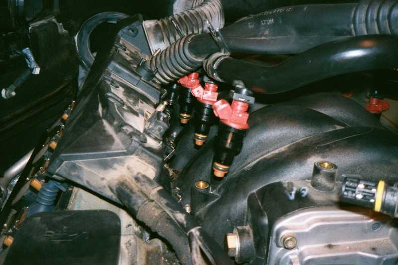
13. Someone with M62 engine repair/rebuild experience should tackle the job of replacing the fuel injectors. They are sometimes difficult to remove/un-snap, and gasoline left in the fuel rails will leak out during this procedure. You will need a small container to collect the excess gasoline.
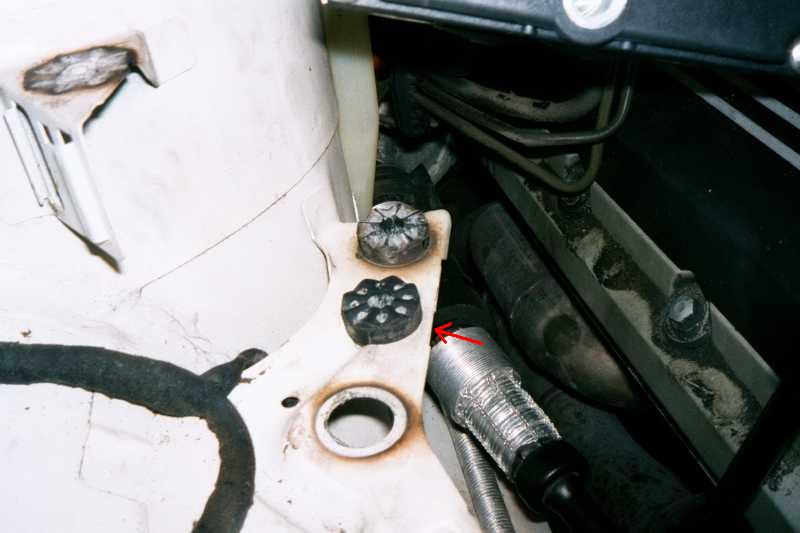
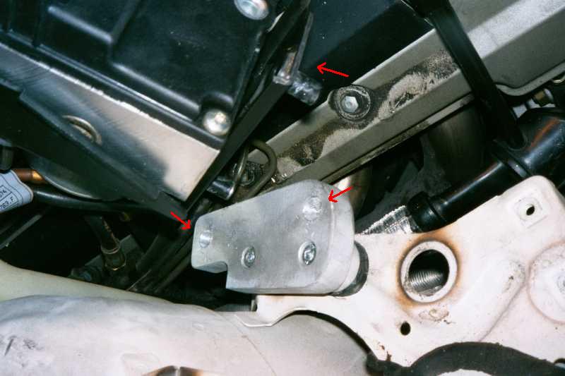
14. These pictures will help you get a better idea of where to drill the large hole and how the new bracket will be mounted. Following the bracket mounting, we had to enlarge the receiving holes in the new bracket with a drill (2nd pic) to allow the mounting pins to fit properly. I believe we also used a Dremel tool to trim the existing mounting bracket a bit. This is semi-visible in the 2nd pic.
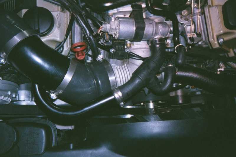
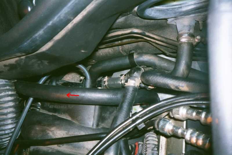
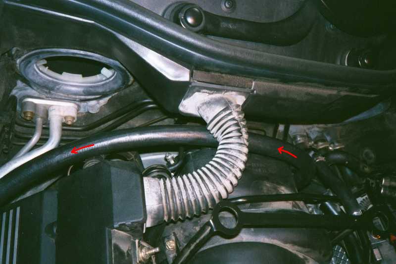
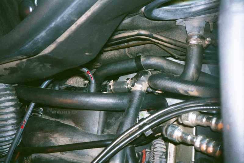
16. Use these pictures to determine the routing path for the breather hose. I'm not absolutely sure where the tie-wraps went.
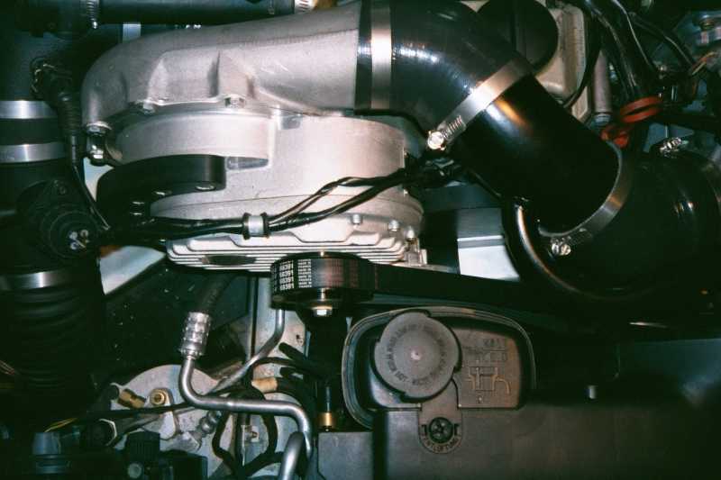
18. The ESS tech used shims to reposition the belt tensioner just a bit for perfect belt alignment. I didn't watch this step closely, so I'm only 50% sure of why it was necessary to do so. If your mechanic would like details, I'd recommend you contact ESS. For the belt installation, I believe it was first wrapped onto the main pulley and SC pulley, then lifted onto the tensioner. Your mechanic will probably be better at installing these belts than I am.
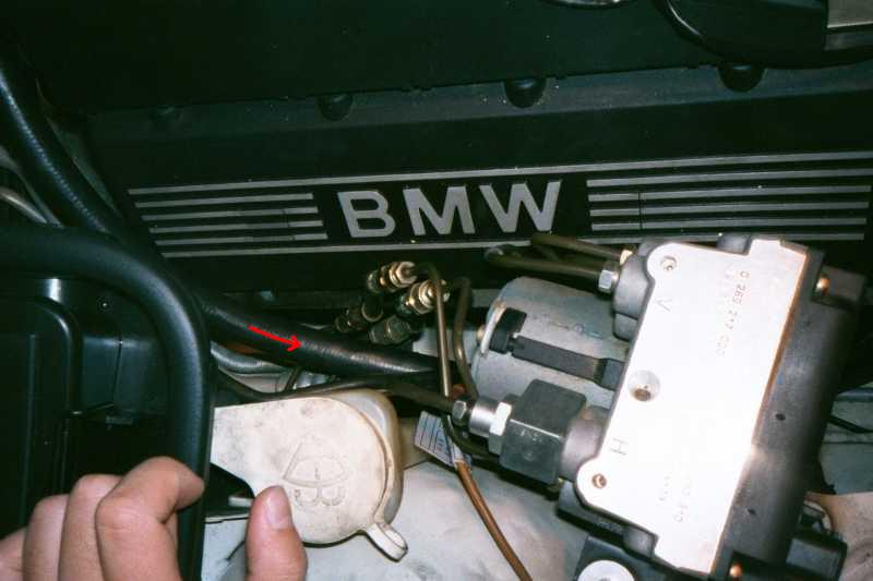
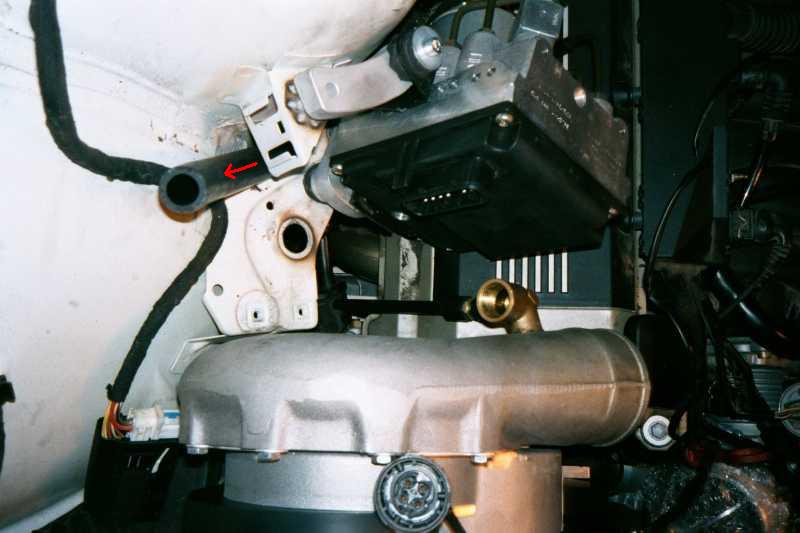
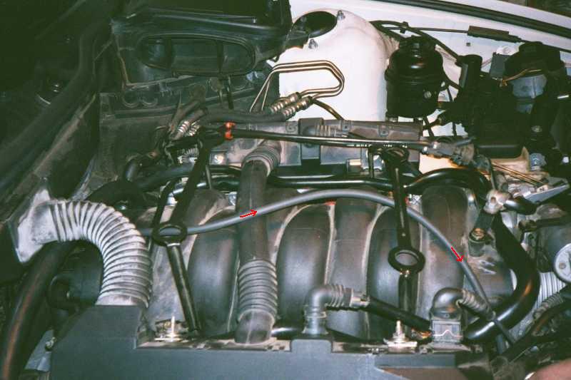
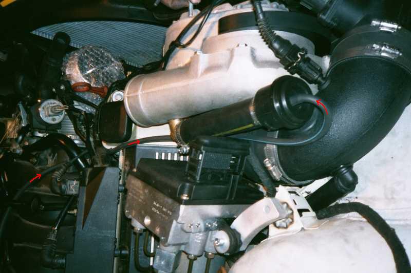
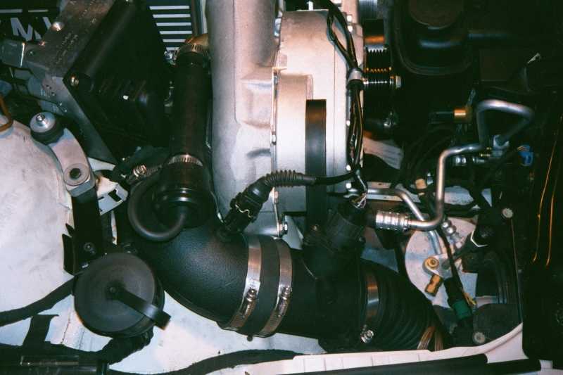
20. Use these pictures to determine the routing path for the bypass valve vacuum line. On a 1999 540i, there was an extra vacuum line that needed to be fed from the rear intake manifold cover. ESS is now supplying a Y-connector to be installed back near the manifold cover if necessary. Align the intake tubing properly so that the temperature sensor, bypass valve, and MAF connector doesn't come in contact with the hood when closed.
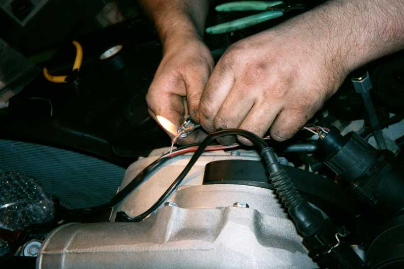
21. On the two cars I've seen, the MAF signal wire was actually grey with a yellow stripe (different from the ESS manual). The supplied ESS wire connectors are not the standard crimp-type. They contain solder in a flame-resistant sleeve. The ESS tech pushed the two stripped wires together towards the center of the connector and used a lighter to melt the solder and shrink the sleeve at the same time. I've never seen wire connectors like this before.
24. The idle might be slightly rough for the first 5-50 miles until the ECU has fully adjusted to the SC installation.
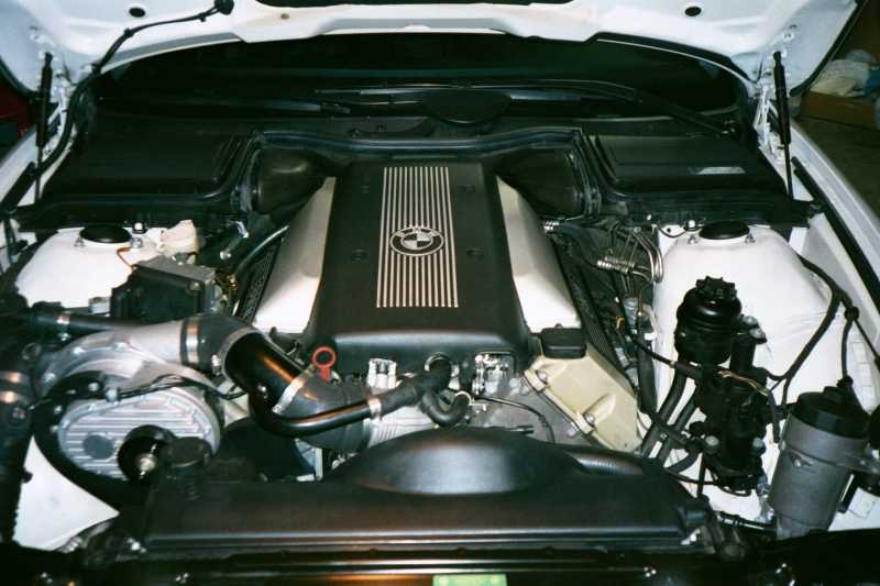
Some pictures of the completed install and camera-shy ESS tech: